CrystalKit
CrystalKitX Version 2 represents a major upgrade of CrystalKitX. The program has been completely rewritten and expanded to include many new features. As with Tempas, CrystalKit is available to run under both macOS and Windows. Version 2 is a paid upgrade from Version 1.
The user manual can be downloaded here: CrystalKit Version 2 Manual
CrystalKit is a program that dramatically decreases the time involved in building crystalline defects of various kinds, from point defects to grain boundaries and precipitates. The program starts from single crystal data, which can be entered within the program or read in from structure files, MacTempas file format, CIF file format, and XYZ file format. Any final structure generated by CrystalKit can be saved as a MacTempas file, an EMS supercell file, a CIF file, or a XYZ file for immediate simulation of diffraction patterns and High Resolution TEM images.
The program will create interface structures using data from two (or one) crystal structures. A geometric grain boundary involving several thousand atoms can be generated in a matter of minutes by specifying the orientation relation between the grains, the interface plane, and the zone-axis. Individual grains can further be freely rotated and translated, and constraints can be set on the distance of the grain to the interface plane. Individual atoms or columns of atoms can be deleted or moved within the interface structure. Atoms can also be added at any location within the structure. A number of additional tools exist for modifying the structure. There is a tool to create an arbitrary path interface. One crystalline structure can become a precipitate in another structure. In the end, when the user has arranged the structure to his/her satisfaction, a unit cell can be marked with the "Define Unit Cell Tool". This unit cell can then be written out as a MacTempas structure file ready for further work.
Example Screenshots from CrystalKit

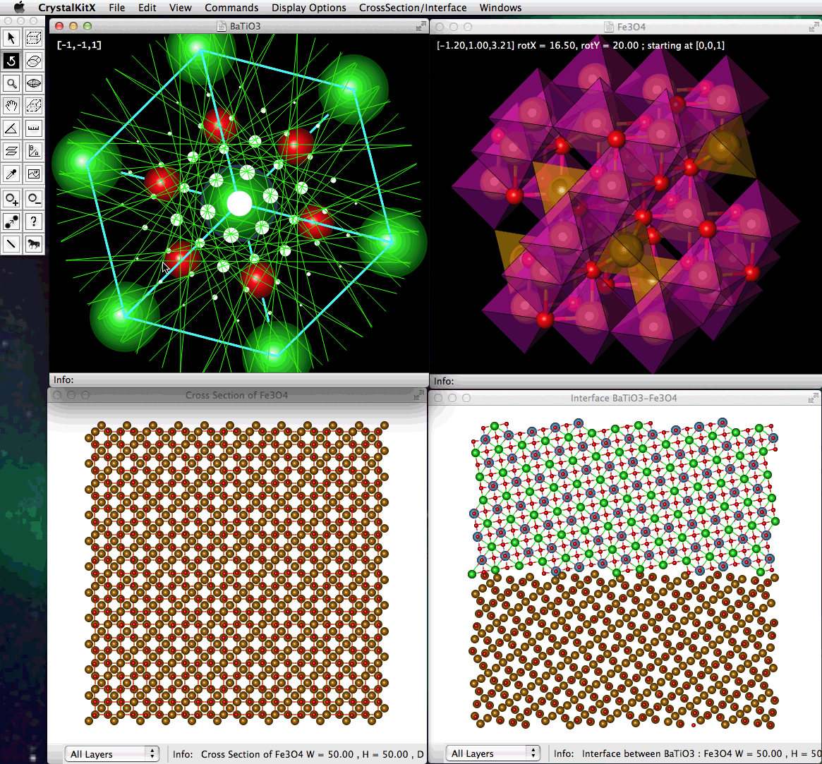
An example of 4 open windows, two of them showing crystal Unit Cells, one displaying a specified Cross-Section View, and finally a displayed model of an Interface between 2 structures.

An example of 4 different windows, three of them showing crystal Unit Cells, one displaying a computed Kinematical CBED Pattern.

Display of a Single Unit Cell of a perfect Crystal (CoSi2) showing coordination tetrahedras around the Si atoms.

The same model used in the previous image showing a perfect Crystal (CoSi2) with coordination tetrahedras around the Si Atoms. In addition, the reciprocal lattice (approximation of the "Diffraction Pattern") is shown and rotates with the crystalline model.

Display of a Single Unit Cell of a LiFePO4 crystal showing the [111] plane, together with the window that controls the display of the plane.

Display of a created Carbon Nano-tube together with the window used in specifying the parameters for the nano-tube. The chirality, diameter of the wall, number of walls etc. are easily specified.

Model of an interface between two structures showing a selection specified by an oval cylinder. In this instance, the atoms within the cylinder are dimmed.

Display of a Cube-Octahedra Particle together with the window used in specifying the parameters for the particle. The size of the particle, chemical element, and the Bond-Distance specify the particle.

The same particle shown above is used together with a 3D rectangular box selection to modify the shape of the particle.

Example of a reconstructed particle showing some options for displaying the 3D surface of the particle.